Sight Scale Factor
Calculator
Calculate the Sight Scale Factor (SSF) for Applied Ballistics from a tall target tracking test. Correct for scope tracking errors with a single linear correction instead of introducing non-linear solver errors.
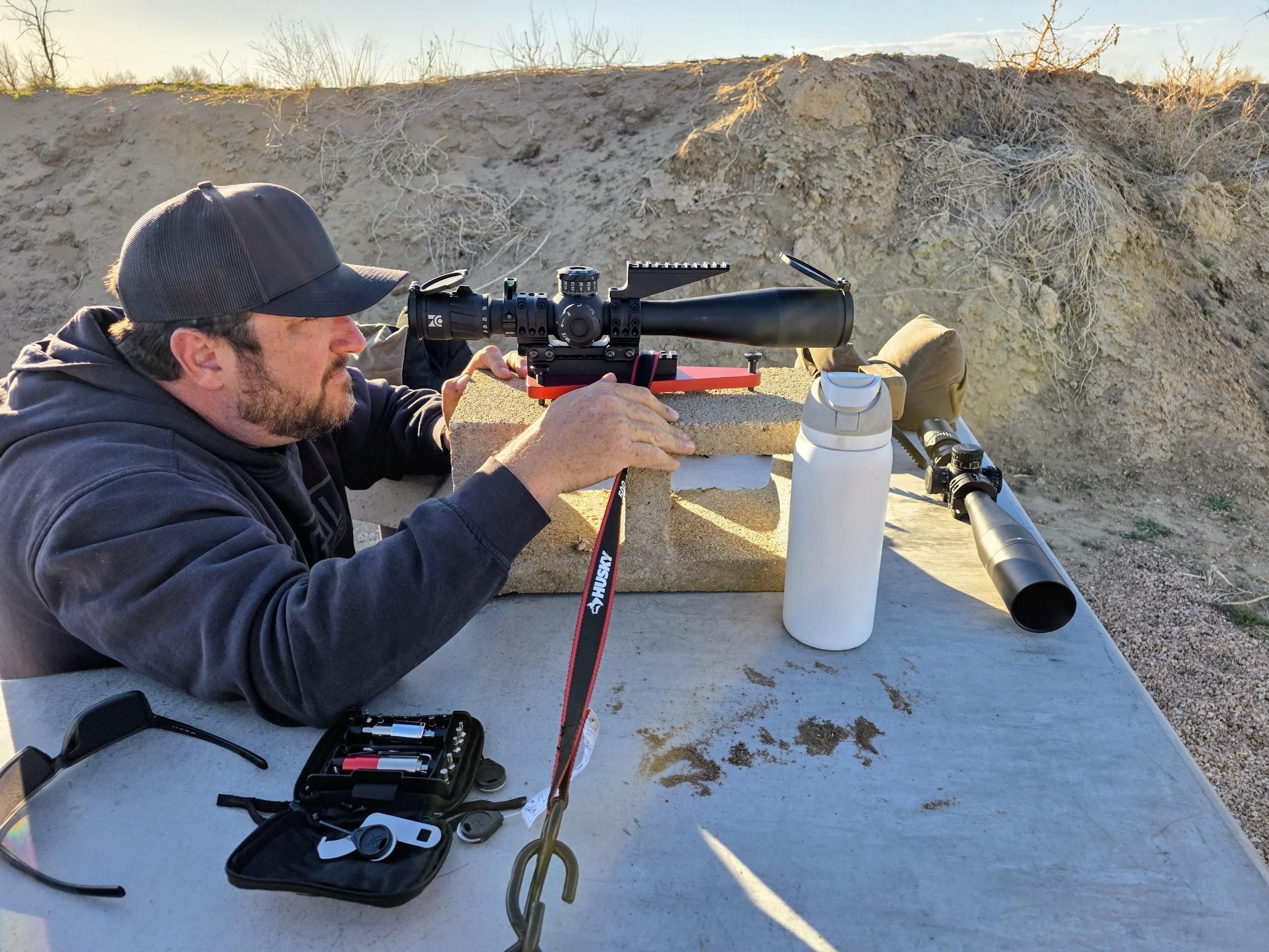
Tracking test setup — scope mounted on a Badger Ordnance Dead Level, secured to the table with a ratchet strap over cinder blocks
The Problem: Scope Tracking Error
Every riflescope has an erector system that physically moves to adjust your point of aim when you dial the turret. When you dial 1.0 mils of elevation, you expect the reticle to move exactly 1.0 mils. In reality, manufacturing tolerances, erector spring tension, and mechanical play mean that many scopes do not track perfectly. A scope might actually move 0.98 mils or 1.03 mils for every 1.0 mil you dial.
At close range, this error is negligible. At long range, it compounds. If your scope over-tracks by 2.5% and you dial 12.0 mils for a 1,000-yard shot, the scope actually moves 12.3 mils — an extra 0.3 mils that puts your bullet approximately 10.8 inches high of your intended target. At 1,500 yards that same 2.5% error on a ~22 mil solution becomes 0.55 mils, or roughly 29 inches of error. Misses like these are routinely blamed on bad ballistic data, wind reads, or bad luck — when the real culprit is a scope that simply does not move the amount it claims to.
A tall target test (also called a tracking test) is the only way to objectively quantify how accurately your scope tracks. It compares what the turret says it dialed to what the scope actually moved. From this measurement, you calculate the Sight Scale Factor (SSF) — a single value that tells a ballistic solver to compensate for the tracking error.
Why Not Just Adjust Muzzle Velocity, BC, or Drop Scale Factor?
When shooters notice their impacts do not match their solver’s predictions, the most common reaction is to “true” the solution by tweaking muzzle velocity (MV), ballistic coefficient (BC), Custom Drag Factor / Drop Scale Factor (DSF) in Applied Ballistics, or Axial Form Factor (i₁) in Hornady 4DOF. This can make impacts match at one specific distance, but it introduces errors at every other distance because these parameters affect the trajectory non-linearly.
Muzzle velocity, BC, and drag-related parameters control how fast the bullet decelerates through the air. Their effect on drop is governed by physics: drag increases with the square of velocity, and time of flight grows exponentially with range. When you artificially inflate MV or BC to compensate for a scope that under-tracks, you are bending the trajectory curve to force-fit one data point. The curve will be wrong everywhere else — too flat at short range, too steep at extreme range, or vice versa.
Sight Scale Factor is fundamentally different. It is a simple linear correction applied to every dial-up value the solver produces. If SSF is 0.975, the solver divides every elevation solution by 0.975 before presenting it to you — effectively increasing each dial-up by about 2.56%. The correction is the same percentage at every distance. This is mathematically correct because scope tracking error is a mechanical property of the erector system — it is a constant percentage of whatever you dial, not a function of bullet flight physics.
Green line (SSF correction): A constant percentage adjustment at every range. The error
between the true solution and the SSF-corrected solution is zero everywhere because the scope’s mechanical error
is a fixed ratio.
Red line (MV / BC / DSF truing): Artificially adjusting muzzle velocity, BC, or a drag scale
factor forces the solver’s curve through a single calibration point (shown at 700 yd). At all other distances
the curve diverges because the physics of bullet drag are non-linear. The error grows in both directions
away from the truing point.
Where Can You Enter Sight Scale Factor?
The Sight Scale Factor input exists in Applied Ballistics Quantum (the mobile app) and in most devices that have Applied Ballistics built in, including the Garmin Foretrex, Kestrel 5700 Elite with Applied Ballistics, Sig Sauer BDX system, and Revic ballistic devices. Look for a field labeled “Sight Scale Factor” or “SSF” in the rifle/scope profile settings.
The following applications do not have a Sight Scale Factor input:
| APPLICATION | SSF INPUT | NOTES |
|---|---|---|
| Applied Ballistics Quantum | YES | Found in weapon profile → Sight Scale Factor |
| Kestrel 5700 Elite (AB) | YES | Gun profile → SSF setting |
| Garmin Foretrex (AB) | YES | Rifle settings → Sight Scale Factor |
| Revic (AB) | YES | Rifle profile settings |
| Hornady 4DOF | NO | No SSF input. Only option is to adjust Axial Form Factor (i₁), which introduces non-linear errors. |
| GeoBallistics (Ballistic AE) | NO | No SSF input. Truing requires adjusting MV or BC. |
| Strelok Pro | NO | No SSF input. Manual truing only through MV/BC/CD adjustments. |
If your solver does not support SSF, you are limited to non-linear truing methods. This does not mean your solver is unusable — it means you should be aware that truing at one distance may introduce small errors at others, and you should verify at multiple distances when possible.
A Note on Methods
There are many different methods for performing a tracking test. What follows is the method I have found works best for me after experimenting with several approaches. It prioritizes accuracy and repeatability above all else. Your mileage may vary, and you are welcome to adapt the procedure to your own situation — but the principles below explain why each decision was made so you can make informed trade-offs if you deviate.
Why 100 Yards Instead of 25 Yards?
You can absolutely measure 20 mils of scope travel at 25 yards — you just need a target that is 4× smaller. At 25 yards, 20 mils subtends 18 inches. At 100 yards, 20 mils subtends 72 inches (which is why the CATS target is 79″ tall). The angular measurement is the same either way. The problem is that two sources of error both scale unfavorably at shorter distances.
1. Target printing and scaling errors are amplified. Any physical target has manufacturing tolerances — the graduation marks are not placed with infinite precision. Suppose the target has a printing error of 0.05 inches (about 1.3 mm) over the full 20-mil span. On a 100-yard target where the 20-mil span is 72 inches, that 0.05-inch error is:
0.05 ÷ 72 = 0.069% target scale error → 0.069% SSF error
On a 25-yard target where the 20-mil span is only 18 inches, that same 0.05-inch error is:
0.05 ÷ 18 = 0.278% target scale error → 0.278% SSF error
That is a 4× amplification of any target manufacturing imperfection. The smaller the target, the more any physical printing error dominates your measurement. This applies to paper stretch from humidity, creases from folding, and any warping of the backing surface as well.
2. Distance measurement precision is 4× more critical. As explained in the laser rangefinder section, range measurement error translates directly to SSF error as a percentage. The same tape measure with the same ±0.25 yard precision gives you very different SSF accuracy at different distances:
At 100 yards: ±0.25 yd = ±0.25% SSF error
At 25 yards: ±0.25 yd = ±1.0% SSF error
A 1% SSF error at 25 yards is the same magnitude as the tracking error you are trying to measure in many scopes. At 100 yards, the same tape measure gives you 4× better precision in your final SSF value. The math is straightforward: every error source that has a fixed physical size — target printing tolerance, tape measure precision, crosshair alignment — becomes a larger percentage of the measurement at shorter distances. Testing at 100 yards minimizes all of these simultaneously.
Why Remove the Scope From the Rifle?
The tracking test measures a property of the scope alone — how accurately the erector system moves when you turn the turret. Any movement of the scope during the test that is not caused by the turret dial will appear as a tracking error and corrupt your result. Even 0.01 mils of scope movement from any other source translates directly into SSF error.
A rifle chassis, stock, and bipod system are designed to balance rigidity, weight, ergonomics, and portability. These are all engineering compromises. A bipod allows some flex. A chassis has thermal expansion. A sling stud can shift under load. None of these are problems when shooting — they are normal — but during a tracking test, any movement at all is indistinguishable from scope tracking error.
The Badger Ordnance Dead Level provides a short, rigid Picatinny rail that can be strapped directly to a solid table with a ratchet strap. It has no flex, no bipod, no barrel, no chassis — nothing that can move. When you dial the turret, the only thing that moves is the erector. This isolates the variable you are trying to measure and ensures that the SSF value you calculate reflects the scope’s actual tracking performance and nothing else.
- Horus Vision CATS Target (Elevation): horusvision.com — A precision-printed tall target with mil and MOA scales spanning 20 mils / 66 MOA. The target is 79″ tall by 38″ wide, printed on a single sheet of paper that will arrive folded.
- Badger Ordnance Dead Level Reticle Leveling Device: badgerordnance.com — A precision Picatinny-mount fixture that holds the scope rigidly for the test without needing to fire the rifle.
- 100 Meter / 330 Foot Tape Measure: Amazon — A 100 meter tape measure is recommended over a 100 yard tape measure to allow some additional length if needed. Physical tape measurement is mandatory — see why a laser rangefinder is not accurate enough.
- 4’ × 8’ Plywood, OSB, or MDF Board: Available at Home Depot or Lowe’s for $10 – $25. This provides a rigid, flat backing surface for the target.
- Ratchet Strap: Amazon — Used to rigidly secure the Dead Level mount to a table. Absolute stability is critical.
- (Optional) Cinder Block: To raise the Dead Level off the table surface to a comfortable viewing height and to align with the target center.
- (Optional) Laminate the CATS Target: Take the target to an office supply store (FedEx, Staples, etc.) and have it laminated. This prevents the paper from ripping in wind and allows the target to be reused for future tests.
- Staple the Horus CATS target to the 4’×8’ board. Align the 20 mil / 66 MOA line near the top of the board, not near the ground. You want the top reference line at eye level or slightly above when the board is standing upright. This ensures the entire scale is usable without bending down or losing sight picture.
- Mount the scope to the Badger Dead Level Picatinny rail. Use proper ring torque specs. The scope must be mounted exactly as it would be on your rifle — same rings, same torque, same position.
- Place the target exactly 100 yards from the scope erector assembly. The measurement point on the scope is the erector assembly — this is the point where light is focused inside the scope, roughly in the middle of the main tube. Use the 100 meter tape measure for this purpose and be as precise as possible. The tape must be completely unobstructed and taut between the scope and the target — do not route it around any obstacles, as this will change the measured length. The target must be both horizontally and vertically true — it cannot be tilted or angled in any direction. Use a carpenter’s level against the vertical and horizontal lines on the target to verify.
DO NOT use a laser rangefinder. It does not have the accuracy necessary for this test. See the detailed explanation below for why even a ±0.5 yard LRF translates to unacceptable SSF error. A digital tape measure will not work outside in direct sunlight (the IR sensor is overwhelmed). Do not trust your range to have the targets at the correct distances. YOU MUST MEASURE. Do not trust your laser rangefinder no matter how much it cost. Use a tape measure for this purpose or do not bother performing this test.
- Set the Badger Dead Level on top of a cinder block on top of a table. The cinder block raises the scope to a comfortable height and helps align it with the center of the target board.
- Wrap a ratchet strap over the Picatinny rail and around the underside of the table. Tension it as tight as possible. The goal is to make the mount absolutely immobile. The scope cannot move during the test — even the slightest shift will appear as a tracking error and corrupt your results. If the table rocks, shim it. If it is windy, use a wind break or wait for calm conditions.
- Align the crosshairs with the 20 mil / 66 MOA reference line at the top of the target. The vertical crosshair should follow the vertical centerline of the target perfectly. The horizontal crosshair should sit precisely on the 20 mil (or 66 MOA) graduation. Use the adjustable feet on the Badger Dead Level to level the scope to the target. The bubble level on the Dead Level can generally be ignored for this step — you are not concerned with the scope being level relative to gravity, only with the scope being perfectly aligned to the target. If the vertical crosshair tracks exactly along the vertical centerline of the target as you dial, the alignment is correct. Take your time with this — it is the reference point for the entire test.
- Dial your elevation turret down until the horizontal crosshair aligns with the 0 mil / 0 MOA line near the bottom of the target. Watch the vertical crosshair as you dial — it should track perfectly along the vertical centerline. If it wanders left or right, this is most likely the scope not being perfectly aligned to the vertical line on the target, not a windage tracking error. Go back to the previous step and verify the scope is perfectly aligned with the target’s vertical centerline before concluding there is a windage tracking issue. A true windage tracking error is possible but rare compared to a simple alignment problem.
- Read the turret. Look at how many mils (or MOA) your turret indicates you have dialed. If the turret reads exactly 20.0 mils (or 66.0 MOA), your scope is tracking perfectly and your SSF is 1.000. If the turret reads a different value — for example, 20.5 mils — then your scope is not tracking perfectly.
This is not a crisis. Most scopes have some tracking error. You can compensate for it by entering the Sight Scale Factor (SSF) into Applied Ballistics. Use the calculator at the top of this page to compute your SSF value.
The Accuracy Math
The tracking test measures how precisely your scope moves over a known angular distance. Because the angular distance on the CATS target is fixed, any error in the range measurement (the distance between the scope and the target) directly corrupts the result. The relationship is:
SSF error % ≈ Range measurement error %
At 100 yards, an angular measurement (mil or MOA) subtends a fixed linear size on the target. If your target is actually at 99.5 yards instead of 100 yards, the angular subtension of the target marks changes by 0.5%. That 0.5% appears directly as SSF error. For a scope that truly tracks at SSF = 0.980 (2% error), a 0.5% range measurement error turns your calculated SSF into somewhere between 0.975 and 0.985 — enough to halve the effectiveness of the correction or over-correct.
Laser rangefinders at 100 yards are not accurate enough. Most commercial LRFs specify accuracy as ±1 yard, and many specify ±0.5 yards. At 100 yards:
±1 yard error at 100 yards = ±1.0% error in SSF
±0.5 yard error at 100 yards = ±0.5% error in SSF
±0.1 yard (tape measure precision) = ±0.1% error in SSF
A 1% error in SSF on a 15-mil dial-up (roughly 1,000 yards for many cartridges) is 0.15 mils, which is about 5.4 inches of impact error. At 1,500 yards that becomes roughly 8+ inches. The whole point of measuring SSF is to remove errors of this magnitude — using a measurement tool that introduces errors of the same magnitude defeats the purpose entirely.
Digital tape measures (laser-based distance tools) also will not work outdoors in direct sunlight. Their infrared sensors are overwhelmed by solar IR, causing erratic or inaccurate readings. A physical tape measure — steel or fiberglass — is the only tool that provides the required accuracy in field conditions.
Do not trust range markings at your shooting facility. Many ranges have target lines that are only approximately placed. A 2-yard error at a “100 yard” line is a 2% SSF error. Measure it yourself with a tape measure or do not perform this test.
Why SSF Works at Every Range
Scope tracking error is a mechanical property of the erector system. When the erector moves, it moves a fixed percentage more or less than it should — regardless of how far you dialed. If a scope over-tracks by 2%, it over-tracks by 2% whether you dial 2 mils or 20 mils. The error is proportional to the dialed value, which makes it a linear function.
A ballistic solver computes an elevation solution in angular units (mils or MOA). That solution is the correct angle assuming the scope moves exactly the amount you tell it to. If the scope does not move that exact amount, you need to tell the solver to pre-compensate. SSF does this by adjusting the angular solution:
Corrected Dial-Up = Solver Elevation ÷ SSF
If SSF is 0.975 (scope under-tracks by 2.5%), every elevation solution is divided by 0.975 — effectively telling you to dial 2.56% more — so that the scope’s reduced movement lands you exactly where the solver intended. Because the correction is a constant divisor applied to the solver output (which scales with range), the correction is always exactly the right proportion at every distance.
Why Adjusting MV, BC, DSF, or Axial Form Factor Fails Across Ranges
Muzzle velocity controls how fast the bullet starts and thus how long it takes to reach each distance. Ballistic coefficient and drag-related factors control how quickly the bullet decelerates. Both of these affect the trajectory through the physics of aerodynamic drag, which is fundamentally non-linear:
Drag Force ∝ V² — drag grows with the square of velocity
Time of Flight ∝ exponential function of range and drag
Bullet Drop ∝ ½ × g × TOF² — drop grows with the square of TOF
When you increase MV by 20 fps to match an observed impact at 700 yards, the solver now computes a faster bullet at every range. But the effect of that 20 fps is small at 200 yards and large at 1,500 yards — not proportionally the same. Similarly, adjusting BC or DSF changes the drag curve’s shape, which affects nearby ranges differently than distant ranges.
The result is that non-linear truing introduces a systematic pattern of errors: you match at your truing distance, but you are too high or too low at ranges above and below that distance. These errors grow with the distance from your truing point. If you true at 700 yards, your 1,500-yard solution may be off by several inches in the opposite direction of your original error. You have traded one problem for another.
If your impacts are off and you have not performed a tracking test, you cannot know whether the error is in the scope tracking, the ballistic model inputs, the environmental conditions, or something else. Performing the tracking test and applying SSF removes one variable from the equation completely, allowing you to isolate the remaining sources of error.